Working on points is fundamental for surveyors and professionals alike. Let's look at how an addon for ZWCAD can help you with this task
ZWGeo is an application running exclusively on ZWCAD Professional, designed for working with maps, coordinates, or just points. It's used by surveyors and people who need tools for creating spatial projects. In today's article, we'll deal exclusively with the aspect of points, coordinates, their description, and the creation of lists.

I'll use a fragment of the terrain to test the tools of our application. A similar model was used in our other article regarding describing contours and creating a terrain profile.
Manage points
The first panel, after loading the application, is about managing points. From the version for ZWCAD 2025 onwards, our applications need to be loaded, either by launching from a dedicated icon on the desktop or through the Load function, which is located on the ribbon.

Under the points tab in ZWGeo, there are a number of commands to help you with your CAD project work. These range from functions for inserting points to creating tables or exporting and importing to external files.
Let's first start by setting the point style with the DDPTYPE command, so that the points are clearly visible.
Points
Once we have a point style established, let's look at the ZWGeo features. The first three functions allow you to insert and describe points. The Quick point command inserts a point with an ascending number. It doesn't require any values to be entered we simply run the command and click anywhere.
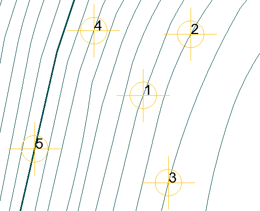
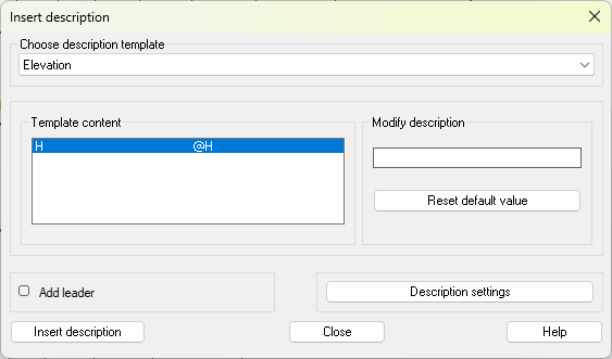
The Describe command allows you to describe a point with any value. ZWGeo offers several templates, such as Elevation, Quick Point, Point, XY Coordinates and XYZ Coordinates.
Let's take a look at one of these templates:
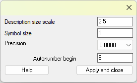
Clicking on settings will show you a special window:
By clicking Insert description, you'll need to indicate where the point will be located.
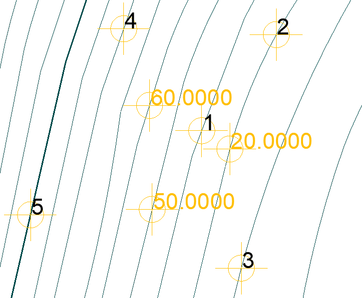
We can modify the description slightly in the template itself to show more than just a numerical value. Let's look at an example of a Z coordinate with a manually extended description:
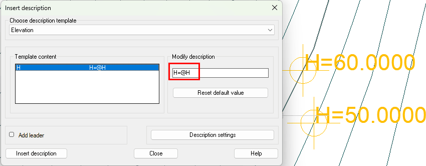
The Add point command is slightly different. Here, you need to indicate the series designation and the starting number. Alternatively, you can click on a point to continue numbering.
Polecenie: ZWGEO:Mark
Serie or select to continue: A
Start number <1>:
Pick point A1:
Select block or write symbol name: _regen
Polecenie:
Pick point A2:
Select block or write symbol name: _regen
Points will be inserted with the height marked and named according to the guidelines given.
Interpolate
ZWGeo allows you to plot the heights of points in a drawing based on interpolation. Just as the levels are assigned heights, the places between them are not. However, we can describe a point at such a location using the Interpolate command.
Run the command, then indicate 3 points which will form a triangle. Clicking inside the triangle will then insert points with heights.
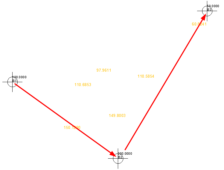
In the example above, I've inserted points with the Add point command, to which I assigned the appropriate height. I then selected them according to the arrows, and after selecting three points, I was able to click inside, and ZWCAD calculated the height of my point.
Table of points
On the ZWCAD ribbon under the ZWGeo tab, there are two commands for creating a table. Report as table allows you to create a simple list of points somewhere in the drawing. When you run the command, select the points you want in the table and confirm with Enter. Then all you have to do is select a location on the drawing, et voilà.
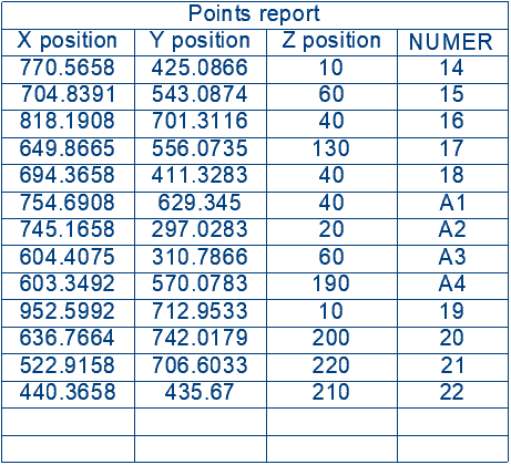
The table is, of course, fully editable. Due to the structure of this command and ZWCAD's, the command may not work correctly when a different language version of the programme and addon is used.
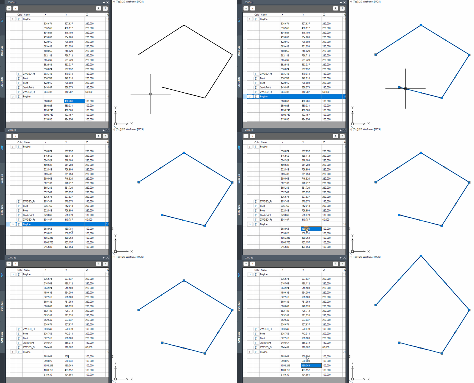
The second command for creating tables is Table of points. This function opens a panel in ZWCAD where all the points and polylines we've added will be located, along with their exact coordinates.
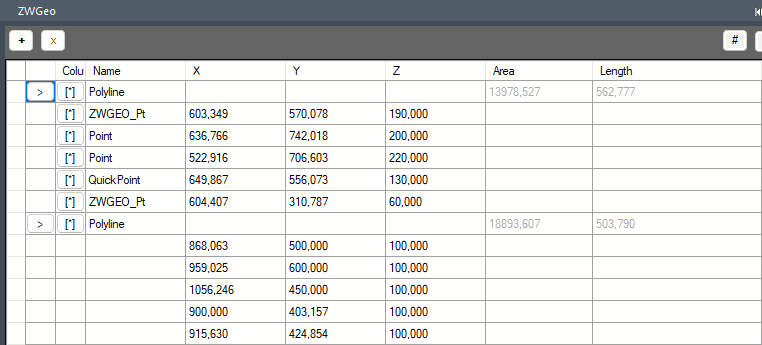
In addition to the coordinates of the points and vertices of the polyline, we also have its length and areas. The last two fields are purely informative, but we can easily edit the coordinates in real time.
Summary
Of course, ZWGeo extends ZWCAD with many more commands related to points, coordinates, and polylines. You can read more about them in our other articles. All the features included in our application were consulted with surveyors and other users of the programme, so we're confident that they realistically help in the design process.
I encourage you to test for yourself; the application is available as a trial for 30 days, just like ZWCAD.

