Working on points, contour lines, elevation, and coordinates is an integral aspect of most surveying projects. ZWGeo addon for ZWCAD help surveyors and cartographers around the world in their work
The ZWGeo application is an addon designed for ZWCAD Professional that extends the content of the programme with commands concerning points, lines, and coordinates, options for importing and exporting them to external files, and tools for describing different types of objects. In this case it'll be contour lines and elevation. Today we will take a look at the tools offered by ZWGeo to help you work on a sample section of a contour map in a CAD drawing. Our addon works only under ZWCAD Professional of similar version.
ZWGeo application
Once the application is installed, launch it either via a dedicated icon on the desktop or an option from the Load panel. This solution ensures that our addons don't slow down ZWCAD start-up when they aren't needed, for example, when previewing CAD drawings.
ZWGeo gives access to two ribbon menus: ZWGeo and ZWGis. For the purpose of this article, we'll focus on the Profile and Manage Points tabs and the basic ZWCAD tools.

Inserting elevation points and coordinates
The Insert Points function will enable us to insert points with a specific series name at selected locations. When working on new drawings, it's a good idea to first go into the point style settings and set the graphic designation that suits us. The function in our CAD programme that enables this is DDPTYPE.
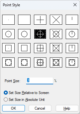
With the style set, we move on to the Add points command. This allows you to insert an arbitrarily named series of points containing the height of an object at a chosen location.
After running the command, the ZWGeo addon will ask us to enter a series — either a new one or an existing one. We can then change the default numerical value of our first point. After confirming with Enter, we move on to selecting a location. Once we have clicked on our contour line and confirmed with Enter, we can either select further locations or terminate the command. We can set up as many elevation points on isolines as we need. Let's look at what the command line looks like after inserting such a point:
Command: ZWGEO:Mark
Serie or select to continue: A
Start number <1>:
Pick point A1:
Select block or write symbol name: _regen
Command:
Pick point A2: *Cancel*
Function cancelled
Point placed on a contour line with a specified elevation will show its coordinates together with the selected markings. Double-clicking will open a menu where you can conveniently modify the description or other aspects of the inserted point in a CAD drawing.
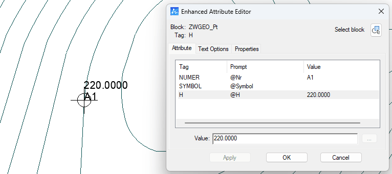
This tool is used to describe height, but what about when we need something else, such as coordinates? Then we use the second function, Describe points. Once launched, this is the menu that will open:
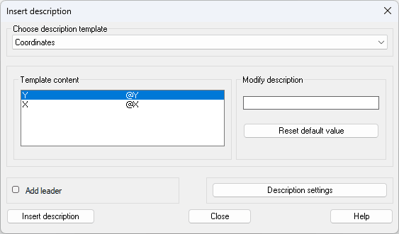
Here, we can select one of several templates, in this case simple X and Y coordinates. The tool allows us to modify the description or add a reference line. It also allows us to change the options that are responsible for font size, starting number or accuracy.
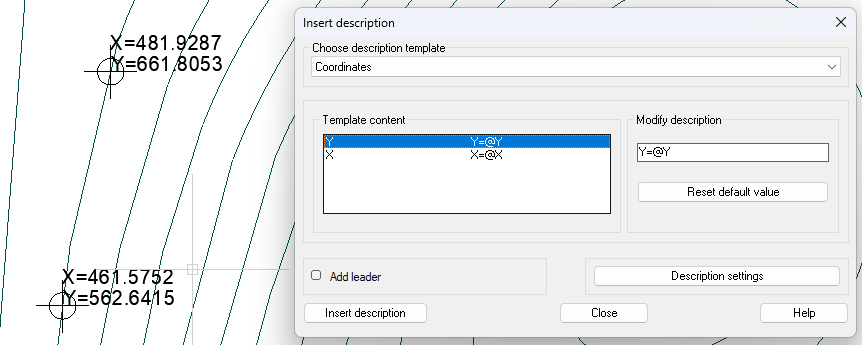
As an exercise, I modified the description slightly to display the X and Y coordinate descriptions by adding X= and Y= at the beginning of the description.
Determining and describing contours
The first tool from the Profile tab in ZWGeo is Mark contour line. This command allows you to easily change the height of an isoline with a single click. A very useful function, which we'll now use, is Label contour lines. This function applies an elevation description with a veil along the selected line to all intersecting contour lines. Let's look at how it works first:
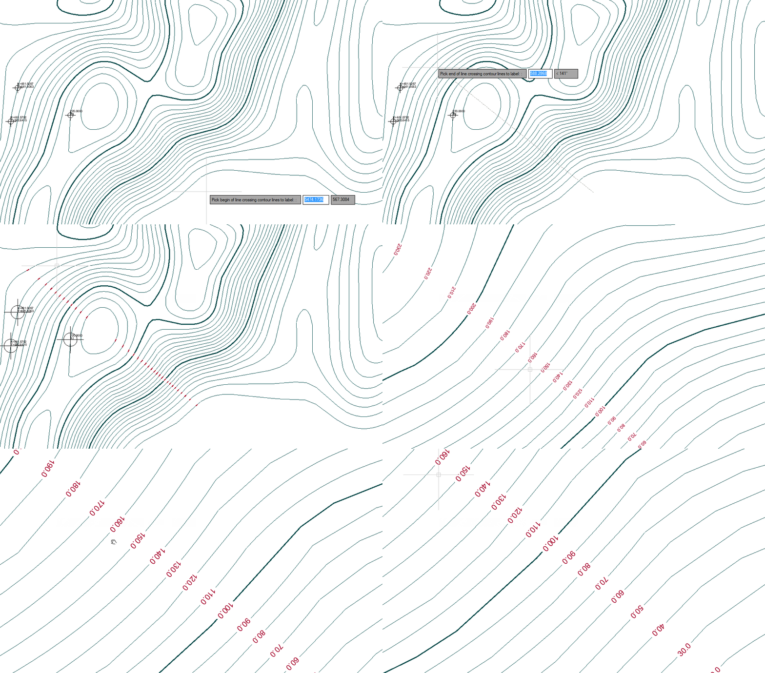
As we can see, the tool is very simple yet effective. The text described depends on the CAD drawing settings such as text style, layer colour, etc., so you can easily adapt it to your needs. Make sure to set the height of isolines with Mark contour lines first.
Drawing a cross-section
ZWGeo also allows you to place a profile of a selected area on our CAD drawing. To do this, start the function, then select a line that will be used as a base for cross-section, and a graph will be created.
As an example, I made a cross-section of the terrain across the entire section and a second cross-section along the lines of the contours labeled earlier. This is what they look like:
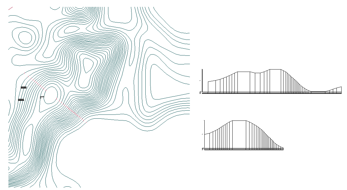
When we zoom in, we can see details such as elevation, distance, or starting altitude.

It's just a few functions of the application, but I hope that you found something interesting in this guide. If so, I encourage you to give our application a chance, and test it yourself. ZWGeo is available here in Polish or English and requires ZWCAD Professional of suitable version.
You can also read more about ZWGeo functions concerning points and coordinates here.

