ZWGeo is an application for ZWCAD that allows, among other things, the insertion of markings into terrain features in a simple way. Let's take a look at this
The ZWGeo application is an addon to ZWCAD Professional that provides surveyors with many tools to improve their work. We've written about our addon before, regarding describing contour lines and working on coordinates and points. Today we'll look at options for describing and marking things such as pipes, cables, fences, etc.
Inserting points at a specific distance
One of the functions of ZWGeo is to insert points on a polyline at a specified distance. I'll use this tool to insert manholes without pre-measuring.
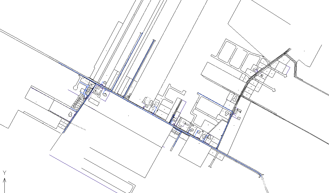
Let's look at a section of the drawing:
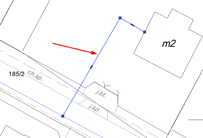
I'll insert two points on the selected line. The first will be at a distance of 10m and the second will be 22m from the beginning of the line. To do this, I'll run the Points by distance command, then select a polyline and specify the value 10. A confirmation of the inserted point will appear in the command line.
Command: ZWGeo:PointsByDistance
Select polyline:
Write distence: 10
(3690.78 6582.33 -107.62)
I then selected the value 22 and completed the command. Points were inserted at the given locations according to my point style.
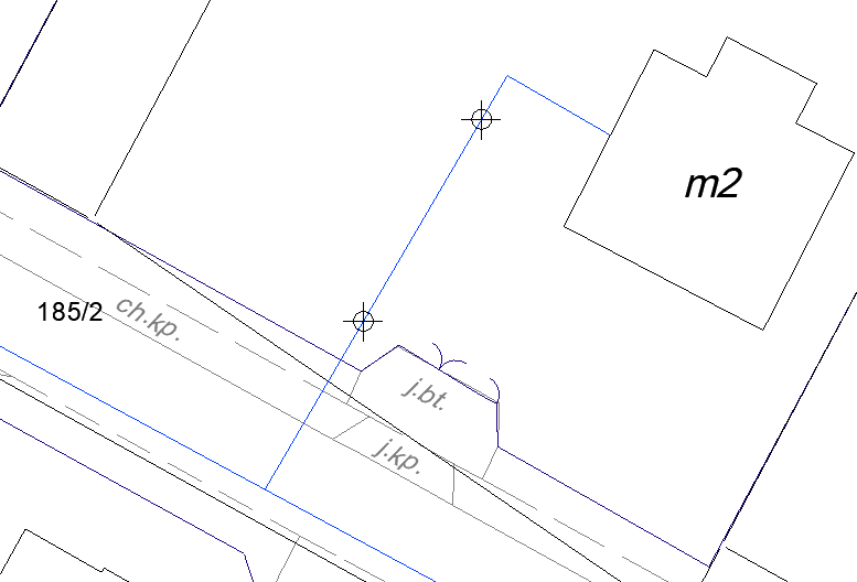
At these points, I can insert my manhole symbol and delete points using the basic tools of our CAD programme.
Inserting a parcel boundary
This time, the functions on the Tools tab will come in handy, more specifically, Mark a boundary.
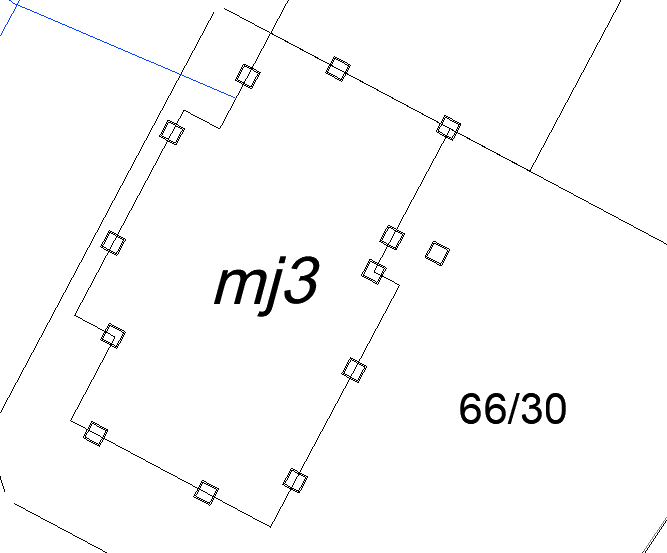
The command allows you to mark any polyline within a specified interval with an object of your choice. This can be another polyline or a block, but for this example, I'll use a block.
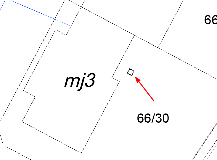
The operation of the function may seem complicated, so I always recommend looking at the command line, which suggests the next steps. So you should:
- Run the command in ZWCAD.
- Select the fence symbol and confirm with Enter.
- Enter its base point.
- Type or specify the distance with two clicks.
- Point to the fence polylines and confirm with Enter.
Our CAD programme with the ZWGeo addon includes another similar solution, the Mark middles function, which is used to describe the centres of polyline segments with any block.
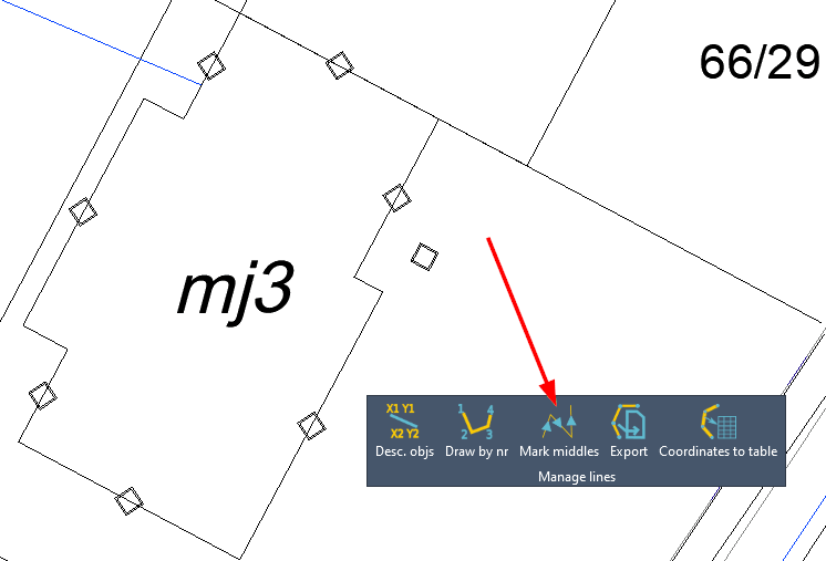
All you have to do is run the command, choose a block then a polyline. It's middle sections will be marked with chosen block.
Describing cables, pipes and similar objects
For describing these types of elements, we've prepared the Front measure and Describe conduit functions, both also in the Tools panel.
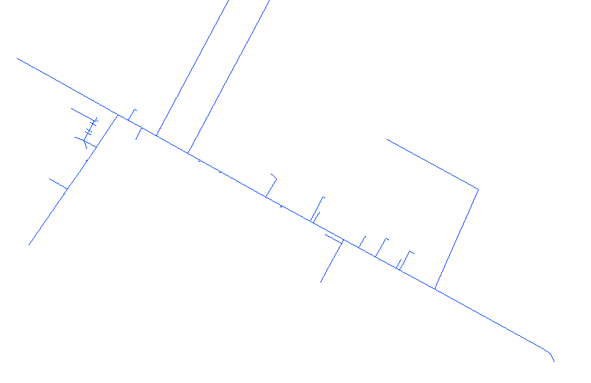
I've turned off the visibility of all layers in my CAD drawing except the one containing the pipes. Now it's left to use the Front measure function found on the ZWGeo ribbon.
Front measure
This function describes the selected lines by their length. In the middle of each polyline segment, the length of that segment will appear slightly above the line itself, so that it's readable.
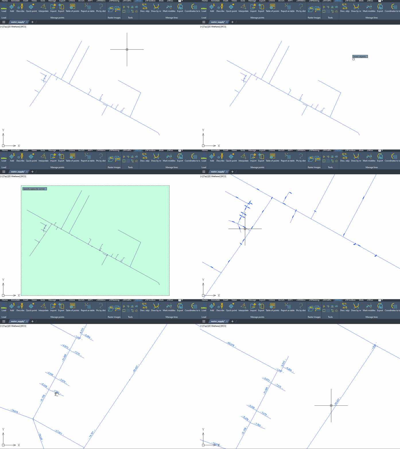
There is a second tool that you may find useful, which is Describe conduit.
Describe conduit
This command is very similar to the previous one, but it describes the centres of the polyline with the name of the layer they are on. In addition, the text is inserted on the mask, making it readable.
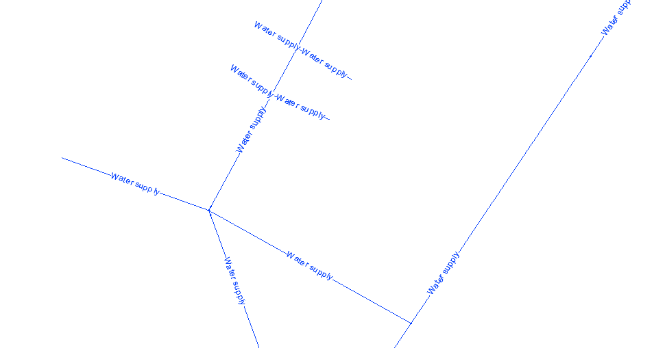
The flow of the command is analogous to Describe conduit. Select the command from the ZWCAD ribbon or by typing ZWGEO:LAYERLABEL, then select the objects and confirm with Enter.
It may happen that an object is described in reverse; in this situation, reverse the polyline by using the PEDIT command.
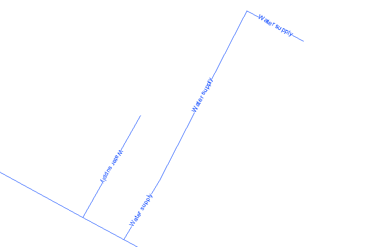
After running the command, point to the polylines and select R for Reverse.
Enter an option [Edit vertices/Close/Decurve/Fit/Join/Linetype-mode/Reverse/Spline/Taper/Width/Undo] <eXit>: r
The course of the polyline on the CAD drawing will be reversed, so the direction of the inscription when inserted will also be different.
These are just a few of the features found in our ZWGeo. I encourage you to test for yourself, and also to check out other guides regarding this ZWCAD addon.
Both the ZWGeo and ZWCAD Professional applications are available as trial versions, so you can test the functionality yourself, which I encourage you to do.

