Let's find out how to easy it is to nest objects on a sheet in CAD drawing
Optimising the layout of objects on a sheet is no easy task. There are many ways to maximise the efficiency of a sheet for cutting objects from it, but today we'll show you how to do this using the ZWNesting addon for ZWCAD Professional.
What is nesting?
Nesting is a method of optimally placing objects on a sheet in order to maximise cutting efficiency while minimising waste. It's very popular in the carpentry industry, but also in basically any other manufacturing sector. When we need to cut plates from a metal sheet or wooden parts from chipboard, MDF or plywood, the right tool comes in handy. Arranging the parts manually takes a lot of time and doesn't give the best result. With the right programme, we can save not only time, but also space on the sheet used, reducing material discard. Our solution for that is ZWNesting application.
Let's take a look at a prepared and well-optimised example sheet:

Here we have an example of a finished sheet that has been filled in with sample objects. We can therefore imagine how long it would take to do this by hand.
So what does the ZWNesting application has to offer?
We can install the ZWNesting application in our ZWCAD Professional. It will add such a panel to the ribbon:
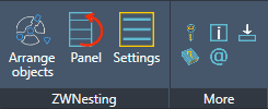
To begin with, a brief explanation of how our programme works, i.e. how to arrange the objects we need on the sheet with a few clicks.
The first method, the simplest one, requires us to perform three steps:
- Run the command.
- Click on the sheet.
- Select objects and confirm with Enter.
Simple? Sure it is. The application allows you to arrange objects such as blocks or closed polylines.
Let's now see how this method works in practice:
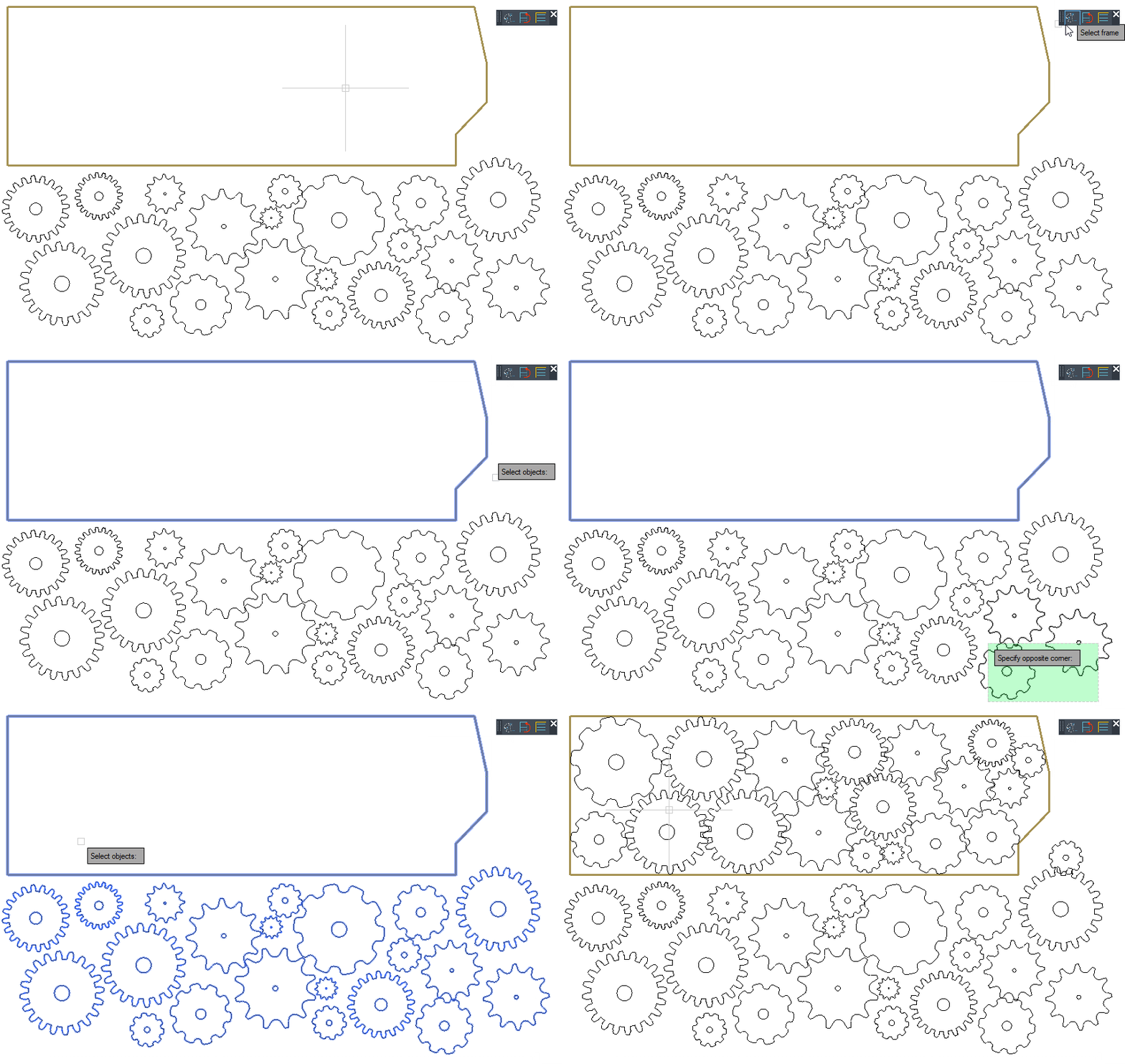
As we can see after running the command I selected the frame, then the objects and the programme did the rest. The animation is of course sped up, but we have the full statistics of the calculation in the command line.

Here we can see how long it took ZWCAD to calculate our layout variants. I can tell you from experience that this time is very dependent on the number and complexity of the parts, the options set, the processing power of a PC and even what else is in the drawing. In this case, it was only 22 seconds, but on large projects, I have sometimes waited up to 20 minutes. Of course, this is still much faster than doing it manually, but the time can be reduced by cleaning up the drawing with the PURGE command, changing the options, or even setting the maximum allowed calculation time. However, we will talk about options later.
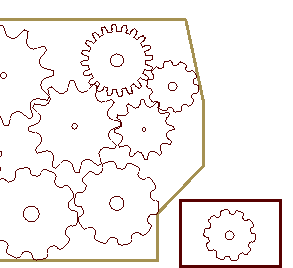
The next thing we see in the command line is the number of objects selected, placed, and discarded. The programme tries to fit as many items as possible, and places those for which it does not find space on the right side of the sheet:
Second method
If we have several of the same parts in our CAD drawing that we want to lay out on the sheet, we can use the second method.
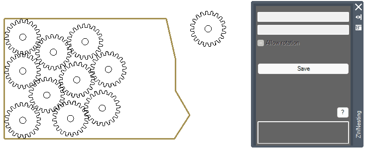
For this, we'll use the second function that ZWNesting offers, which is the panel. Let's take a look at it:
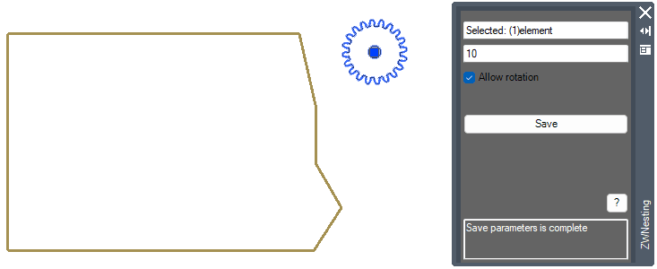
Once an object has been selected, we can choose how many copies are to be inserted into the sheet by our application. In addition, we can select whether it can be rotated or not. After saving, we get a confirmation in the bar at the bottom. It's important to remember to use a copy of the object or, when finished, to restore it to its standard value by writing a value of 1 on the object.
So let's look at what the nesting process looks like in this example:
Of course, we aren't limited to one object here; we can choose several and assign a different number of copies to each.
ZWNesting also offers us extensive options
The third function in the overlay is options. Let's take a look at what we can modify for our addon and what the default parameters look like:
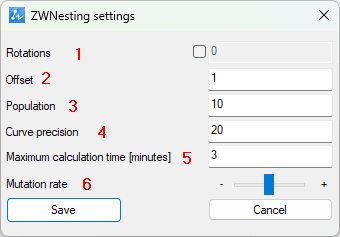
- The rotation angle of our objects. By default, the elements aren't rotated, but you can set, for example, 45 so that the programme can rotate the selected elements by 45 degrees to find the best solution.
- This is the offset of objects from each other by a certain number of units in the CAD drawing. It's a good idea to set several units for example to match thickness or to make sure cutting is easier.
- The number of iterations ZWCAD will perform when looking for the best alignment. The more we choose, the greater the chance of the most optimal alignment, but the calculation time may increase considerably.
- Precision of arcs and circles. For these types of objects, the programme selects a number of points that it aligns. If the precision is too low, you may find that some elements will overlap. From experience, I know that the default value should be quite sufficient.
-
The maximum time after which the programme will not seek another variant. Useful for long and complex calculations. It's worth mentioning here that during each calculation, a panel appears which, when clicked, stops the process of placing objects in the drawing.
-
The slider is responsible for selecting the order in which objects are placed. We can control the priority for large and small parts.
So, as we can see, there are some possibilities here. Usually it will be a good idea to include object rotations, possibly increasing the number of attempts.
Potential problems in working with the programme
It can certainly happen that the calculation takes too long. As I have already written, there can be many factors involved, and the nesting process uses as much as it can of the computer's processing power. When ZWNesting is running, we can't use our CAD programme; we have to wait until the whole thing is finished, but this can be interrupted by clicking on the window in the middle of the sheet:
![]()
ZWNesting also adds a progress bar in the bottom left corner. It can stand at 0% for a long time, but it's not worth worrying about this; it's just the initial preparation that the programme undertakes. The rest of the calculations will go faster.
In the case of very small elements, the addon may fail to place objects in the sheet, even though, by eye, they will fit. If this happens and it is possible, it is worth scaling the whole thing to a larger size.
When working on blocks, you may find that some objects overlap. This may be due to how ZWCAD and ZWNesting recognise which part of the block to use for layout. If the block consists of several closed areas, the programme selects the largest as the base element. Let's look at an example:
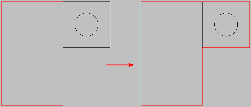
By default, the application would treat the left rectangle as the base, so the right part could overlap either the sheet border or other objects. In this case, it's sufficient to just outline the object with a polyline. Remember that ZWNesting works with closed objects, so in the case of imprecise drawings where the lines don't close or overlap, small inaccuracies may also appear.
That's probably it for our solution for ZWCAD regarding object optimisation. The ZWNesting addon for ZWCAD can be downloaded for self-testing; it will run in full version for 30 days, so it's worth seeing for yourself if you find it useful. The programme can be downloaded from this page, there is also a manual and a handful of basic information.

