Our ZWCAD addon allows you to check vehicle passability on CAD drawings, which will certainly prove useful when creating your own traffic projects
When creating CAD projects related to traffic organisation, it'll be useful to check the passability of different types of vehicles. Our ZWTraffic addon provides such a feature, which allows you to test for passability in a number of ways.
In many articles, we've mentioned various features of our application for ZWCAD, I encourage you to take a read. This time I'll use the module to easily create custom roundabout to test vehicle passability on it.
As a reminder, ZWTraffic requires ZWCAD Professional in the same vintage version to work. In the example below, I'm using version 2025.
Creating roundabouts
ZWTraffic adds a number of tools to ZWCAD that make it easier to create road designs, including the creation of roundabouts. Specifically, it's the Islands tab, which is located by default next to a trajectory model that we'll use later.
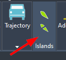
So let's take a look at what the features available here offer:

A total of six possible roundabout accesses are available, varying in shape and use. Each has its own described parameters, which can be edited to suit your needs. Once you have selected your option, you can create such a CAD object and attach it to the roundabout with a single button.
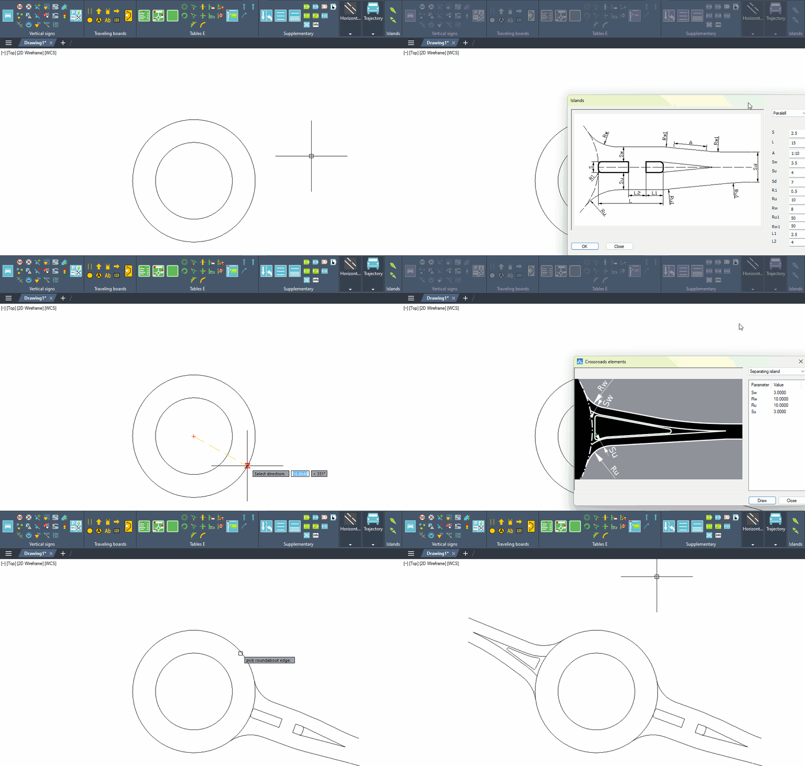
As I mentioned, the process of creating a roundabout road access is extremely simple. To do so, select the function from the Islands panel from the ribbon in ZWCAD and then the appropriate type of access. After clicking on Draw/OK, all you have to do is indicate the outer circle of the roundabout, and it's done.
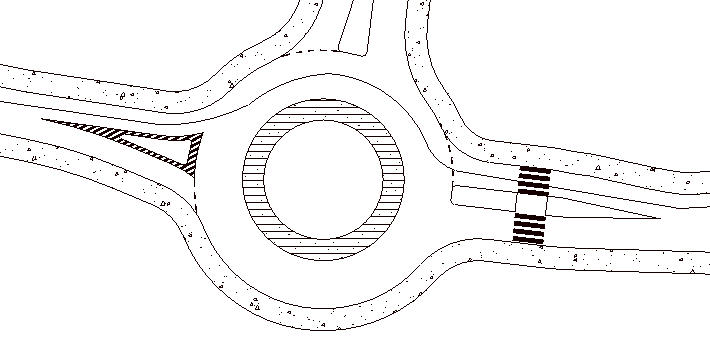
The example below shows how easy this is. All you need is a roundabout constructed from two circles and the ZWTraffic addon.
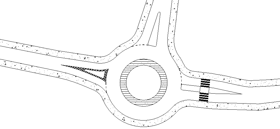
It remains to use the TRIM function to get rid of parts of the circle. I've also added a roadside and hatching. To make the stop line, pedestrian crossing, and exclusion area, I used the ZWTraffic horizontal signs panel, which you can read about here.
What is the Trajectory module anyway?
It's a function found in the Trajectory panel. It allows you to check the path of a vehicle in two different ways. It also allows you to place a preview of the vehicle on the CAD drawing.
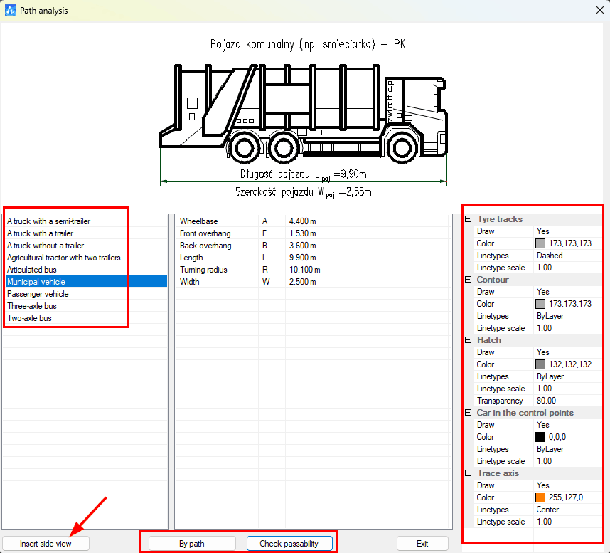
A list of vehicles is available on the left side. It's not possible to edit it, but if necessary, feel free to contact us by email; we're able to prepare additional vehicles. Each of them has specific parameters, which are listed when you select a vehicle. There is a preview at the top, which can be inserted into the drawing using the button on the left.
Next, there are two types of trajectory checks: either by path or manually.
On the right side of the menu are the editable settings of the entire module. You can change the colours of the lines, the layer they're on, or the scale of the line type.
Trajectory By path
The first way to check a trajectory is to select By path. ZWCAD will then ask you to indicate the polyline along which it will pass the selected vehicle to check its trajectory.
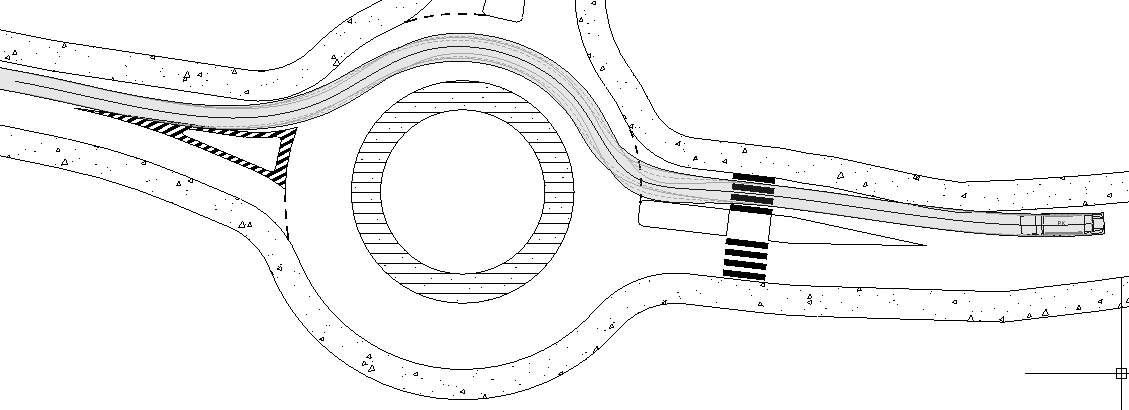
For this purpose, I've drawn a polyline on my roundabout. I'll check the passability of the municipal vehicle on this polyline.
Following the course of the command, I got this result:

As you can see, the specified vehicle has managed to pass this roundabout.
The view of the vehicle is on each point of the polyline, while a spline can also be used:
Check passability
The second method of checking passability in ZWCAD is to select Check passability. With this, it's possible to manually check the vehicle's performance.
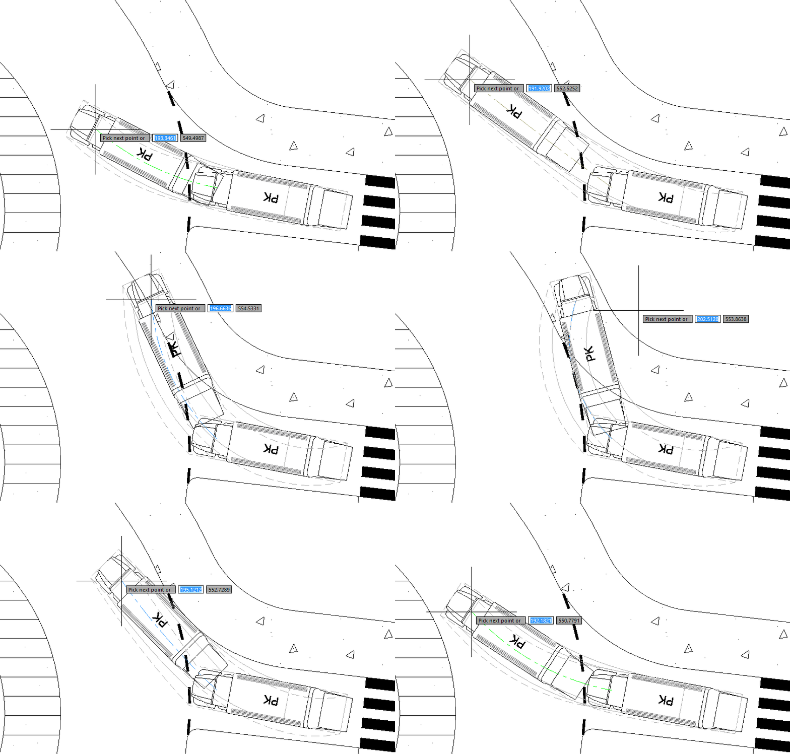
Once the vehicle has been placed in the starting position, ZWCAD will indicate the position of the vehicle under the cursor, and when you click on the CAD drawing, it will be placed there. It's worth paying attention to the colour of the guideline, as it's of great importance:
- a green colour means that the vehicle will fit without any problems,
- orange colour means that speed must be reduced for this maneuver,
- blue colour means that you may need to stop and turn the steering wheel at a standstill.
This is what checking for passability in ZWTraffic looks like, step by step:
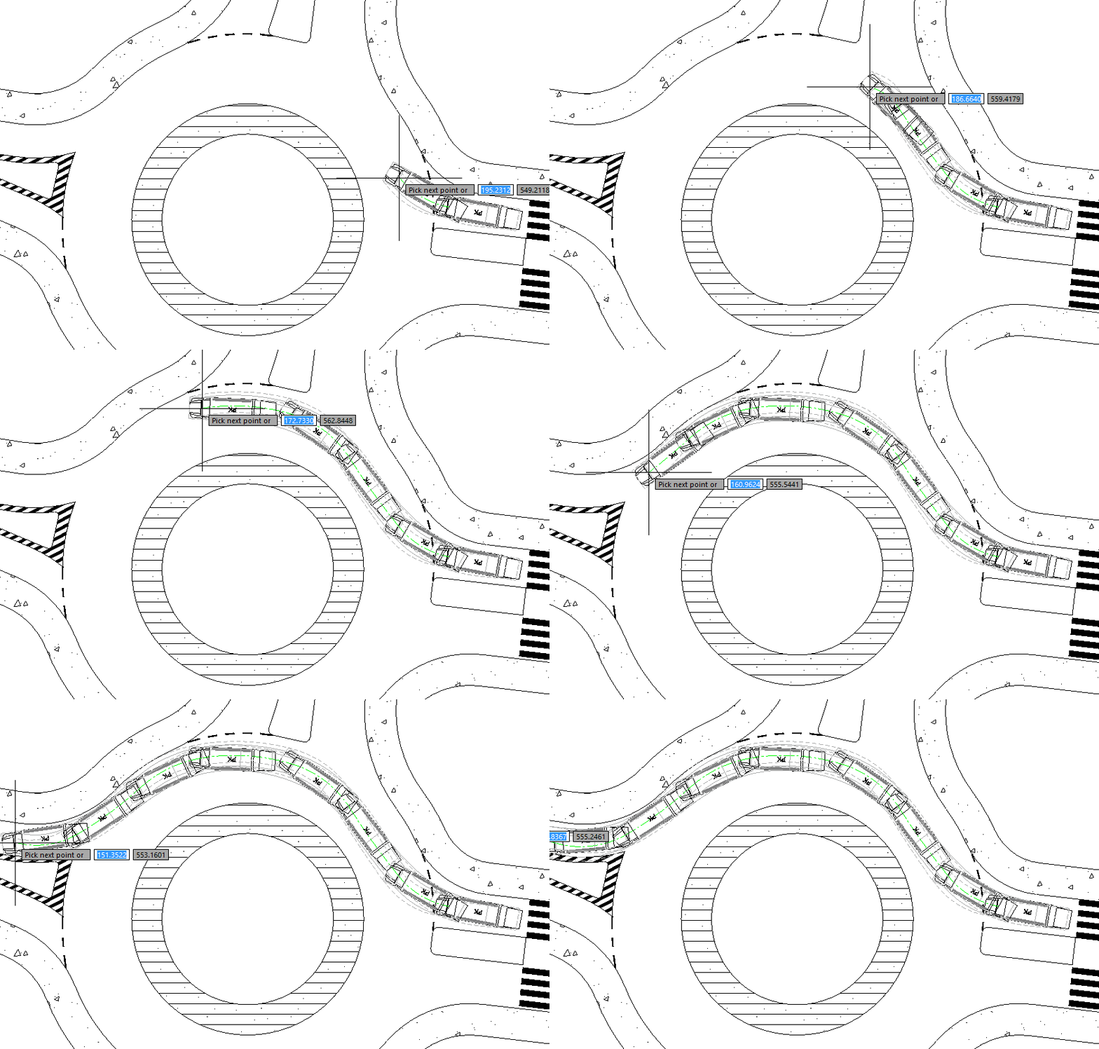
It's worth noting that, for user convenience, objects created via the trajectory module are inserted as a group. In this way, the created formation can be moved or deleted with a single click. In the Extras tab, however, there is a function called Select singly, which can be used to switch the group display, e.g., for editing purposes. You can then edit individual components such as the vehicle, hatching, tyre tracks, etc., and return to displaying as group.
ZWTraffic
I encourage you to test the addon yourself; it's available as a trial version for 30 days just like ZWCAD, which can be downloaded from our website. I also encourage you to browse other articles on the functionality of our application. If you have any questions or concerns, please feel free to email me at This email address is being protected from spambots. You need JavaScript enabled to view it..

